Primeiro, você precisa conectar o monitor ao controlador. Conectamos de acordo com o esquema:
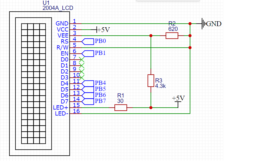
PB0 - PB7 - saídas do controlador.
Exibir atribuição de pinos:
| Número do PIN | Sinal | Atribuição de sinal |
| 1 | GND | Terra (fio comum) |
| 2 | VCC | + 5 |
| 3 | VEE | . . 10-20 , . |
| 4 | RS | : 0 – ; 1 – . |
| 5 | R/W | :
0 – ; 1 – . , . |
| 6 | EN | . , «» . |
| 7 | DB0 | . . |
| 8 | DB1 | |
| 9 | DB2 | |
| 10 | DB3 | |
| 11 | DB4 | . |
| 12 | DB5 | |
| 13 | DB6 | |
| 14 | DB7 | |
| 15 | A | (+) |
| 16 | K | (-). . |
Então, o display está conectado. É hora de ensinar o microcontrolador a trabalhar com ele. Decidi criar minha própria biblioteca para poder utilizá-la em diferentes projetos. Ele consiste em dois arquivos - lcd_20x4.he lcd_20x4.c
Vamos começar com o arquivo de cabeçalho.
#ifndef LCD_LCD_20X4_2004A_LCD_20X4_H_
#define LCD_LCD_20X4_2004A_LCD_20X4_H_

#include "stm32f1xx.h"
#include "delay.h"
No início, incluímos o arquivo de biblioteca CMSIS stm32f1xx.h, pois tenho uma pedra STM32F103C8T6. Com a próxima inclusão, incluímos o arquivo delay.h - esta é minha biblioteca para trabalhar com atrasos com base no cronômetro do sistema. Não vou descrever aqui, aqui está seu código:
Arquivo Delay.h
#ifndef DELAY_DELAY_H_
#define DELAY_DELAY_H_

#include "stm32f1xx.h"

#define F_CPU 72000000UL
#define US F_CPU/1000000
#define MS F_CPU/1000
#define SYSTICK_MAX_VALUE 16777215
#define US_MAX_VALUE SYSTICK_MAX_VALUE/(US)
#define MS_MAX_VALUE SYSTICK_MAX_VALUE/(MS)


void delay_us(uint32_t us); //  233
void delay_ms(uint32_t ms); //  233
void delay_s(uint32_t s);

#endif /* DELAY_DELAY_H_ */
Arquivo Delay.c
#include "delay.h"


/*      */

void delay_us(uint32_t us){ //  233 016

	if (us > US_MAX_VALUE || us == 0)
		return;

	SysTick->CTRL &= ~SysTick_CTRL_TICKINT_Msk; //     0
	SysTick->CTRL |= SysTick_CTRL_CLKSOURCE_Msk; //
	SysTick->LOAD = (US * us-1); //
	SysTick->VAL = 0; //     SYST_CVR
	SysTick->CTRL |= SysTick_CTRL_ENABLE_Msk; //

	while(!(SysTick->CTRL & SysTick_CTRL_COUNTFLAG_Msk)); //    COUNFLAG   SYST_CSR

	SysTick->CTRL &= ~SysTick_CTRL_COUNTFLAG_Msk;	//   COUNTFLAG
	SysTick->CTRL &= ~SysTick_CTRL_ENABLE_Msk; //

}

void delay_ms(uint32_t ms){ //  233

	if(ms > MS_MAX_VALUE || ms ==0)
		return;

	SysTick->CTRL &= ~SysTick_CTRL_TICKINT_Msk;
	SysTick->CTRL |= SysTick_CTRL_CLKSOURCE_Msk;
	SysTick->LOAD = (MS * ms);
	SysTick->VAL = 0;
	SysTick->CTRL |= SysTick_CTRL_ENABLE_Msk;

	while(!(SysTick->CTRL & SysTick_CTRL_COUNTFLAG_Msk));

	SysTick->CTRL &= ~SysTick_CTRL_COUNTFLAG_Msk;
	SysTick->CTRL &= ~SysTick_CTRL_ENABLE_Msk;


}

void delay_s(uint32_t s){

	for(int i=0; i<s*5;i++) delay_ms(200);
}
O display 2004A é baseado no controlador HITACHI HD44780. Portanto, vamos dar uma olhada na folha de dados deste controlador. A Tabela 6 contém o sistema de comandos, bem como os tempos de execução desses comandos.

Vamos reescrever os comandos necessários em macros no arquivo de cabeçalho:
// display commands

#define CLEAR_DISPLAY 0x1
#define RETURN_HOME 0x2
#define ENTRY_MODE_SET 0x6 // mode cursor shift rihgt, display non shift
#define DISPLAY_ON 0xC // non cursor
#define DISPLAY_OFF 0x8
#define CURSOR_SHIFT_LEFT 0x10
#define CURSOR_SHIFT_RIGHT 0x14
#define DISPLAY_SHIFT_LEFT 0x18
#define DISPLAY_SHIFT_RIGHT 0x1C
#define DATA_BUS_4BIT_PAGE0 0x28
#define DATA_BUS_4BIT_PAGE1 0x2A
#define DATA_BUS_8BIT_PAGE0 0x38
#define SET_CGRAM_ADDRESS 0x40 // usage address |= SET_CGRAM_ADDRESS
#define SET_DDRAM_ADDRESS 0x80
Agora você precisa configurar os pinos do controlador para funcionarem com o monitor. Determine a posição dos bits na porta ODR do controlador. Preste atenção ao PIN_D4. Tenho o 10º bit registrado em vez de 4. A 4ª saída não funciona no meu controlador. Não sei ao que está conectado, mas no registrador ODR este bit é sempre um, mesmo antes do início da inicialização do relógio do controlador. Não sei com o que isso está relacionado, talvez a pedra não seja original.
//     ODR
#define PIN_RS 0x1
#define PIN_EN 0x2
#define PIN_D7 0x80
#define PIN_D6 0x40
#define PIN_D5 0x20
#define PIN_D4 0x400
Em seguida, configuramos os registradores de controle para as saídas. Decidi fazer isso na forma de macros de pré-processador:
#define     LCD_PORT               	GPIOB
#define	LCD_ODR 				LCD_PORT->ODR

#define     LCD_PIN_RS()     		LCD_PORT->CRL &= ~GPIO_CRL_CNF0; \
							LCD_PORT->CRL |= GPIO_CRL_MODE0;    // PB0   -,  50

#define     LCD_PIN_EN()            LCD_PORT->CRL &= ~GPIO_CRL_CNF1;\
						 LCD_PORT->CRL |= GPIO_CRL_MODE1;        // PB1

#define     LCD_PIN_D7()            LCD_PORT->CRL &= ~GPIO_CRL_CNF7;\
						 LCD_PORT->CRL |= GPIO_CRL_MODE7;          // PB7

#define     LCD_PIN_D6()            LCD_PORT->CRL &= ~GPIO_CRL_CNF6;\
						 LCD_PORT->CRL |= GPIO_CRL_MODE6;       // PB6

#define     LCD_PIN_D5()            LCD_PORT->CRL &= ~GPIO_CRL_CNF5;\
						 LCD_PORT->CRL |= GPIO_CRL_MODE5;         // PB5

#define     LCD_PIN_D4()            LCD_PORT->CRH &= ~GPIO_CRH_CNF10;\
						 LCD_PORT->CRH |= GPIO_CRH_MODE10;         // PB10

#define     LCD_PIN_MASK   (PIN_RS | PIN_EN | PIN_D7 | PIN_D6 | PIN_D5 | PIN_D4) // 0b0000000011110011
No final do arquivo de cabeçalho, definimos as funções para trabalhar com o display:
void portInit(void); //
void sendByte(char byte, int isData);
void lcdInit(void); //
void sendStr(char *str, int row ); //

#endif /* LCD_LCD_20X4_2004A_LCD_20X4_H_ */
Terminamos com o arquivo de cabeçalho. Agora vamos escrever a implementação das funções no arquivo lcd_20x4.c
O primeiro passo é configurar os pinos para funcionarem com o display. Isso é feito pela função void portInit (void):
void portInit(void){
//----------------------  ----------------------------------------------------

	if(LCD_PORT == GPIOB) RCC->APB2ENR |= RCC_APB2ENR_IOPBEN;
	else if (LCD_PORT == GPIOA) RCC->APB2ENR |= RCC_APB2ENR_IOPAEN;
	else return;

//---------------------    LCD-----------------------------------------------------

		LCD_PIN_RS();//
		LCD_PIN_EN();
		LCD_PIN_D7();
		LCD_PIN_D6();
		LCD_PIN_D5();
		LCD_PIN_D4();

		lcdInit(); //

	return ;
}
Quanto à função lcdInit (), esta é a função de inicialização do display. Vamos escrever também. É baseado em um fluxograma de inicialização de uma tela a partir de uma folha de dados:

//---------------------  -----------------------------------------------------------
void lcdInit(void){


			delay_ms(15); //

			sendByte(0x33, 0); //      0011
			delay_us(100);

			sendByte(0x32, 0); //      00110010
			delay_us(40);

			sendByte(DATA_BUS_4BIT_PAGE0, 0); //   4
			delay_us(40);
			sendByte(DISPLAY_OFF, 0); //
			delay_us(40);
			sendByte(CLEAR_DISPLAY, 0); //
			delay_ms(2);
			sendByte(ENTRY_MODE_SET, 0); //
			delay_us(40);
			sendByte(DISPLAY_ON, 0);//
			delay_us(40);


	return ;
}
A função de inicialização usa a função void sendByte (char byte, int isData). Vamos escrever sua implementação. É baseado em um gráfico de tempo de uma folha de dados:

void sendByte(char byte, int isData){

	//
	LCD_ODR &= ~LCD_PIN_MASK;

	if(isData == 1) LCD_ODR |= PIN_RS; //    RS
		else LCD_ODR &= ~(PIN_RS);		   //   RS

	LCD_ODR |= PIN_EN; //   E

	//

	if(byte & 0x80) LCD_ODR |= PIN_D7;
	if(byte & 0x40) LCD_ODR |= PIN_D6;
	if(byte & 0x20) LCD_ODR |= PIN_D5;
	if(byte & 0x10) LCD_ODR |= PIN_D4;

	LCD_ODR &= ~PIN_EN; //

	LCD_ODR &= ~(LCD_PIN_MASK & ~PIN_RS);//     RS

     	LCD_ODR |= PIN_EN;//   E

	//
	if(byte & 0x8) LCD_ODR |= PIN_D7;
	if(byte & 0x4) LCD_ODR |= PIN_D6;
	if(byte & 0x2) LCD_ODR |= PIN_D5;
	if(byte & 0x1) LCD_ODR |= PIN_D4;

	LCD_ODR &= ~(PIN_EN);//
	delay_us(40);


	return;
}
Agora podemos enviar um byte para o display em um barramento de 4 bits. Este byte pode ser um comando ou um símbolo. É determinado passando a variável isData para a função. É hora de aprender como transferir strings.
O display 2004A consiste em 4 linhas de 20 caracteres conforme refletido no título. Para não complicar a função, não implementarei o corte de linhas para 20 caracteres. Enviaremos uma string de caracteres e uma string para a saída da função.
Para exibir o símbolo na tela, você precisa gravá-lo na DDRAM. O endereçamento DDRAM corresponde à tabela:

void sendStr(char *str, int row ){

	char start_address;

	switch (row) {

	case 1:
		start_address = 0x0; // 1
		break;

	case 2:
		start_address = 0x40; // 2
		break;

	case 3:
		start_address = 0x14; // 3
		break;

	case 4:
		start_address = 0x54; // 4
		break;

	}

	sendByte((start_address |= SET_DDRAM_ADDRESS), 0); //         DDRAM

	delay_ms(4);
	while(*str != '\0'){//

		sendByte(*str, 1);
		str++;


	}// while
}
É isso, a biblioteca do display está pronta. Agora é a hora de usá-lo. Na função main (), escrevemos:
portInit();//

	sendStr("    HELLO, HABR", 1);
	sendStr("     powered by", 2);
	sendStr("   STM32F103C8T6", 3);
	sendStr("Nibiru", 4);
E obtemos o resultado:

Em conclusão, darei uma lista completa dos arquivos:
lcd_20x4.h
#ifndef LCD_LCD_20X4_2004A_LCD_20X4_H_
#define LCD_LCD_20X4_2004A_LCD_20X4_H_

#include "stm32f1xx.h"
#include "delay.h"

// display commands

#define CLEAR_DISPLAY 0x1
#define RETURN_HOME 0x2
#define ENTRY_MODE_SET 0x6 // mode cursor shift rihgt, display non shift
#define DISPLAY_ON 0xC // non cursor
#define DISPLAY_OFF 0x8
#define CURSOR_SHIFT_LEFT 0x10
#define CURSOR_SHIFT_RIGHT 0x14
#define DISPLAY_SHIFT_LEFT 0x18
#define DISPLAY_SHIFT_RIGHT 0x1C
#define DATA_BUS_4BIT_PAGE0 0x28
#define DATA_BUS_4BIT_PAGE1 0x2A
#define DATA_BUS_8BIT_PAGE0 0x38
#define SET_CGRAM_ADDRESS 0x40 // usage address |= SET_CGRAM_ADDRESS
#define SET_DDRAM_ADDRESS 0x80


//     ODR
#define PIN_RS 0x1
#define PIN_EN 0x2
#define PIN_D7 0x80
#define PIN_D6 0x40
#define PIN_D5 0x20
#define PIN_D4 0x400


#define     LCD_PORT               	GPIOB
#define		LCD_ODR 				LCD_PORT->ODR

#define     LCD_PIN_RS()     		LCD_PORT->CRL &= ~GPIO_CRL_CNF0; \
									LCD_PORT->CRL |= GPIO_CRL_MODE0;    // PB0   -,  50

#define     LCD_PIN_EN()            LCD_PORT->CRL &= ~GPIO_CRL_CNF1;\
									LCD_PORT->CRL |= GPIO_CRL_MODE1;        // PB1

#define     LCD_PIN_D7()            LCD_PORT->CRL &= ~GPIO_CRL_CNF7;\
									LCD_PORT->CRL |= GPIO_CRL_MODE7;          // PB7

#define     LCD_PIN_D6()            LCD_PORT->CRL &= ~GPIO_CRL_CNF6;\
									LCD_PORT->CRL |= GPIO_CRL_MODE6;       // PB6

#define     LCD_PIN_D5()            LCD_PORT->CRL &= ~GPIO_CRL_CNF5;\
									LCD_PORT->CRL |= GPIO_CRL_MODE5;         // PB5

#define     LCD_PIN_D4()            LCD_PORT->CRH &= ~GPIO_CRH_CNF10;\
									LCD_PORT->CRH |= GPIO_CRH_MODE10;         // PB10

#define     LCD_PIN_MASK   (PIN_RS | PIN_EN | PIN_D7 | PIN_D6 | PIN_D5 | PIN_D4) // 0b0000000011110011

void portInit(void); //
void sendByte(char byte, int isData);
void lcdInit(void); //
void sendStr(char *str, int row ); //

#endif /* LCD_LCD_20X4_2004A_LCD_20X4_H_ */
lcd_20x4.c
#include "lcd_20x4.h"

//     LCD

void sendByte(char byte, int isData){

	//
	LCD_ODR &= ~LCD_PIN_MASK;

	if(isData == 1) LCD_ODR |= PIN_RS; //    RS
		else LCD_ODR &= ~(PIN_RS);		   //   RS

	//
	if(byte & 0x80) LCD_ODR |= PIN_D7;
	if(byte & 0x40) LCD_ODR |= PIN_D6;
	if(byte & 0x20) LCD_ODR |= PIN_D5;
	if(byte & 0x10) LCD_ODR |= PIN_D4;

	//   E
	LCD_ODR |= PIN_EN;
	LCD_ODR &= ~PIN_EN; //

	//     RS

	LCD_ODR &= ~(LCD_PIN_MASK & ~PIN_RS);

	//
	if(byte & 0x8) LCD_ODR |= PIN_D7;
	if(byte & 0x4) LCD_ODR |= PIN_D6;
	if(byte & 0x2) LCD_ODR |= PIN_D5;
	if(byte & 0x1) LCD_ODR |= PIN_D4;

	//   E

	LCD_ODR |= PIN_EN;
	//delay_us(10);

	//

	LCD_ODR &= ~(PIN_EN);
	delay_us(40);


	return;
}

//               50

void portInit(void){

//----------------------  ----------------------------------------------------

	if(LCD_PORT == GPIOB) RCC->APB2ENR |= RCC_APB2ENR_IOPBEN;
	else if (LCD_PORT == GPIOA) RCC->APB2ENR |= RCC_APB2ENR_IOPAEN;
	else return;

//---------------------    LCD-----------------------------------------------------

		LCD_PIN_RS();
		LCD_PIN_EN();
		LCD_PIN_D7();
		LCD_PIN_D6();
		LCD_PIN_D5();
		LCD_PIN_D4();

		lcdInit();

	return ;
}

//---------------------  -----------------------------------------------------------
void lcdInit(void){

			delay_ms(15); //

			sendByte(0x33, 0); //      0011
			delay_us(100);

			sendByte(0x32, 0); //      00110010
			delay_us(40);

			sendByte(DATA_BUS_4BIT_PAGE0, 0); //   4
			delay_us(40);
			sendByte(DISPLAY_OFF, 0); //
			delay_us(40);
			sendByte(CLEAR_DISPLAY, 0); //
			delay_ms(2);
			sendByte(ENTRY_MODE_SET, 0); //
			delay_us(40);
			sendByte(DISPLAY_ON, 0);//
			delay_us(40);


	return ;
}

void sendStr(char *str, int row ){

	char start_address;

	switch (row) {

	case 1:
		start_address = 0x0; // 1
		break;

	case 2:
		start_address = 0x40; // 2
		break;

	case 3:
		start_address = 0x14; // 3
		break;

	case 4:
		start_address = 0x54; // 4
		break;

	}

	sendByte((start_address |= SET_DDRAM_ADDRESS), 0); //         DDRAM

	delay_ms(4);
	while(*str != '\0'){

		sendByte(*str, 1);
		str++;
		//delay_ms(100);

	}// while
}