Este é meu primeiro artigo sobre Habré, então peço que não joguem objetos pesados. Desde já, obrigado.
Vamos começar com o plano de fundo. Era uma vez eu tive que mudar para microcontroladores ST ARM. Isso se devia ao fato de que PIC e AVR já eram escassos e queriam novas aventuras. Entre os disponíveis em padarias e um grande número de artigos sobre "início rápido", a escolha recaiu sobre o STM32F100.
Estou acostumada a trabalhar no IAR. Sim, existem outros IDEs, mas o recurso IAR é suficiente para mim: um editor relativamente conveniente, não um depurador ruim e é bastante conveniente trabalhar com registros durante a depuração.
Quando tentei fazer o primeiro projeto, fiquei desapontado - CMSIS! Qualquer outra pessoa, mas para mim foi (e continua sendo) horror: muitas faias, estruturas longas e incompreensíveis para mim. Não foi interessante me aprofundar em tudo isso. Tentei compilar alguns exemplos e percebi que esse não é o nosso método.
Não existem outras opções? Há sim. Aquele integrado ao IAR: iostm32f10xx4.he similar inclui. Nada mal:
RCC_APB2ENR_bit.ADC1EN = 1; // ADCTudo o que faltava era enfiá-lo nas aulas e usá-lo. E foi o que ele fez. Depois de algum tempo, demorou para fazer o código para STM32f4xx. E aqui novamente uma emboscada - não há includistas. O que fazer? - escreva você mesmo. Analisei as bibliotecas auto-escritas existentes e decidi fazer de maneira um pouco diferente. É sobre isso que a história será.
Começar
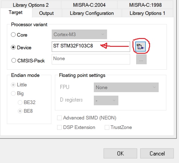
Não vou falar sobre a instalação de IAR e drivers para o depurador. Não há nada novo aqui. Tenho IAR 8 com um limite de código de 32 kB. O controlador STM32F103 instalado na placa de comprimidos plue é selecionado para operação.
Inicie o IAR, crie um projeto c ++, selecione o controlador desejado.O
próximo passo é estudar a documentação. Estaremos interessados no Manual de referência RM0008. O principal é ler com atenção.
Em geral, quando ensinei meus funcionários a programar controladores, dei a tarefa - ligar o LED (conectado à perna do controlador), usar um depurador, editar registros e ler a documentação.
Módulo RCC. Dobrando
Este módulo geralmente é esquecido. Eles se lembram apenas quando é impossível piscar o LED.
Lembrar! Para ligar qualquer periférico, você precisa aplicar pulsos de relógio a ele! Você não pode viver sem ele.
As portas de E / S ficam no barramento APB2. Encontramos na documentação um registro para controlar o clock deste barramento, este é RCC_APB2ENR:

Para habilitar o clock da porta C (o LED está apenas soldado ao PC13), você precisa escrever um no bit IOPCEN.
Agora encontraremos o endereço do registro RCC_APB2ENR. Seu deslocamento é 0x18, o endereço básico para os registradores RCC é 0x40021000.
Para tornar mais conveniente trabalhar com bits, vamos criar uma estrutura:
typedef struct
{
  uint32_t  AFIOEN         : 1;
  uint32_t                 : 1;
  uint32_t  IOPAEN         : 1;
  uint32_t  IOPBEN         : 1;
  uint32_t  IOPCEN         : 1;
  uint32_t  IOPDEN         : 1;
  uint32_t  IOPEEN         : 1;
  uint32_t                 : 2;
  uint32_t  ADC1EN         : 1;
  uint32_t  ADC2EN         : 1;
  uint32_t  TIM1EN         : 1;
  uint32_t  SPI1EN         : 1;
  uint32_t                 : 1;
  uint32_t  USART1EN       : 1;
  uint32_t                 :17;
} RCC_APB2ENR_b;
Para não sofrermos mais tarde, vamos listar imediatamente todos os endereços cadastrais:
enum AddrRCC
{
  RCC_CR          = 0x40021000,
  RCC_CFGR        = 0x40021004,
  RCC_CIR         = 0x40021008,
  RCC_APB2RSTR    = 0x4002100C,
  RCC_APB1RSTR    = 0x40021010,
  RCC_AHBENR      = 0x40021014,
  RCC_APB2ENR     = 0x40021018,
  RCC_APB1ENR     = 0x4002101C,
  RCC_BDCR        = 0x40021020,
  RCC_CSR         = 0x40021024
};
agora resta escrever o código para habilitar os periféricos:
static void EnablePort(uint8_t port_name)
{
  volatile RCC_APB2ENR_b* apb2enr = reinterpret_cast<RCC_APB2ENR_b*>(RCC_APB2ENR);
  switch (port_name)
  {
    case 'A': apb2enr->IOPAEN = 1; break;
    case 'a': apb2enr->IOPAEN = 1; break;
    case 'B': apb2enr->IOPBEN = 1; break;
    case 'b': apb2enr->IOPBEN = 1; break;
    case 'C': apb2enr->IOPCEN = 1; break;
    case 'c': apb2enr->IOPCEN = 1; break;
    case 'D': apb2enr->IOPDEN = 1; break;
    case 'd': apb2enr->IOPDEN = 1; break;
    case 'E': apb2enr->IOPEEN = 1; break;
    case 'e': apb2enr->IOPEEN = 1; break;
  }
}
Ao trabalhar com registradores, não se esqueça dos voláteis , caso contrário, após a otimização pelo compilador, procuraremos por muito tempo os erros e repreenderemos os desenvolvedores do compilador.
Fazemos o mesmo para habilitar o clock de outros periféricos.
Como resultado, obtivemos a seguinte classe (nem tudo está listado):
STM32F1xx_RCC.h
#pragma once
#include "stdint.h"
namespace STM32F1xx
{
  class RCC
  {
  protected:
    enum AddrRCC
    {
      RCC_CR          = 0x40021000,
      RCC_CFGR        = 0x40021004,
      RCC_CIR         = 0x40021008,
      RCC_APB2RSTR    = 0x4002100C,
      RCC_APB1RSTR    = 0x40021010,
      RCC_AHBENR      = 0x40021014,
      RCC_APB2ENR     = 0x40021018,
      RCC_APB1ENR     = 0x4002101C,
      RCC_BDCR        = 0x40021020,
      RCC_CSR         = 0x40021024
    };

    typedef struct {
      uint32_t  HSION          : 1;
      uint32_t  HSIRDY         : 1;
      uint32_t                 : 1;
      uint32_t  HSI_TRIM       : 5;
      uint32_t  HSI_CAL        : 8;
      uint32_t  HSEON          : 1;
      uint32_t  HSERDY         : 1;
      uint32_t  HSEBYP         : 1;
      uint32_t  CSSON          : 1;
      uint32_t                 : 4;
      uint32_t  PLLON          : 1;
      uint32_t  PLLRDY         : 1;
      uint32_t                 : 6;
    } RCC_CR_b;

    typedef struct {
      uint32_t  SW             : 2;
      uint32_t  SWS            : 2;
      uint32_t  HPRE           : 4;
      uint32_t  PPRE1          : 3;
      uint32_t  PPRE2          : 3;
      uint32_t  ADC_PRE        : 2;
      uint32_t  PLLSRC         : 1;
      uint32_t  PLLXTPRE       : 1;
      uint32_t  PLLMUL         : 4;
      uint32_t  USBPRE         : 1;
      uint32_t                 : 1;
      uint32_t  MCO            : 3;
      uint32_t                 : 5;
    } RCC_CFGR_b;

    typedef struct
    {
      uint32_t  TIM2EN         : 1;
      uint32_t  TIM3EN         : 1;
      uint32_t  TIM4EN         : 1;
      uint32_t                 : 8;
      uint32_t  WWDGEN         : 1;
      uint32_t                 : 2;
      uint32_t  SPI2EN         : 1;
      uint32_t                 : 2;
      uint32_t  USART2EN       : 1;
      uint32_t  USART3EN       : 1;
      uint32_t                 : 2;
      uint32_t  I2C1EN         : 1;
      uint32_t  I2C2EN         : 1;
      uint32_t  USBEN          : 1;
      uint32_t                 : 1;
      uint32_t  CANEN          : 1;
      uint32_t                 : 1;
      uint32_t  BKPEN          : 1;
      uint32_t  PWREN          : 1;
      uint32_t                 : 3;
    } RCC_APB1ENR_b;

    typedef struct
    {
      uint32_t  AFIOEN         : 1;
      uint32_t                 : 1;
      uint32_t  IOPAEN         : 1;
      uint32_t  IOPBEN         : 1;
      uint32_t  IOPCEN         : 1;
      uint32_t  IOPDEN         : 1;
      uint32_t  IOPEEN         : 1;
      uint32_t                 : 2;
      uint32_t  ADC1EN         : 1;
      uint32_t  ADC2EN         : 1;
      uint32_t  TIM1EN         : 1;
      uint32_t  SPI1EN         : 1;
      uint32_t                 : 1;
      uint32_t  USART1EN       : 1;
      uint32_t                 :17;
    } RCC_APB2ENR_b;

    typedef struct {
      uint32_t  DMAEN          : 1;
      uint32_t                 : 1;
      uint32_t  SRAMEN         : 1;
      uint32_t                 : 1;
      uint32_t  FLITFEN        : 1;
      uint32_t                 : 1;
      uint32_t  CRCEN          : 1;
      uint32_t                 :25;
    } RCC_AHBENR_r;

  public:
    static void EnablePort(uint8_t port_name)
    {
      volatile RCC_APB2ENR_b* apb2enr = reinterpret_cast<RCC_APB2ENR_b*>(RCC_APB2ENR);
      switch (port_name)
      {
        case 'A': apb2enr->IOPAEN = 1; break;
        case 'a': apb2enr->IOPAEN = 1; break;
        case 'B': apb2enr->IOPBEN = 1; break;
        case 'b': apb2enr->IOPBEN = 1; break;
        case 'C': apb2enr->IOPCEN = 1; break;
        case 'c': apb2enr->IOPCEN = 1; break;
        case 'D': apb2enr->IOPDEN = 1; break;
        case 'd': apb2enr->IOPDEN = 1; break;
        case 'E': apb2enr->IOPEEN = 1; break;
        case 'e': apb2enr->IOPEEN = 1; break;
      }
    }

    static void DisablePort(char port_name)
    {
      volatile RCC_APB2ENR_b* apb2enr = reinterpret_cast<RCC_APB2ENR_b*>(RCC_APB2ENR);
      switch (port_name)
      {
        case 'A': apb2enr->IOPAEN = 0; break;
        case 'a': apb2enr->IOPAEN = 0; break;
        case 'B': apb2enr->IOPBEN = 0; break;
        case 'b': apb2enr->IOPBEN = 0; break;
        case 'C': apb2enr->IOPCEN = 0; break;
        case 'c': apb2enr->IOPCEN = 0; break;
        case 'D': apb2enr->IOPDEN = 0; break;
        case 'd': apb2enr->IOPDEN = 0; break;
        case 'E': apb2enr->IOPEEN = 0; break;
        case 'e': apb2enr->IOPEEN = 0; break;
      }
    }

    static void EnableAFIO()
    {
      volatile RCC_APB2ENR_b* apb2enr = reinterpret_cast<RCC_APB2ENR_b*>(RCC_APB2ENR);
      apb2enr->AFIOEN = 1;
    }

    static void DisableAFIO()
    {
      volatile RCC_APB2ENR_b* apb2enr = reinterpret_cast<RCC_APB2ENR_b*>(RCC_APB2ENR);
      apb2enr->AFIOEN = 0;
    }

    static void EnableI2C(int PortNumber)
    {
      switch (PortNumber)
      {
        case 1:
        {
          volatile RCC_APB1ENR_b* apb1enr = reinterpret_cast<RCC_APB1ENR_b*>(RCC_APB1ENR);
          apb1enr->I2C1EN = 1;
          break;
        }
        case 2:
        {
          volatile RCC_APB1ENR_b* apb1enr = reinterpret_cast<RCC_APB1ENR_b*>(RCC_APB1ENR);
          apb1enr->I2C2EN = 1;
          break;
        }

      }
    }

    static void EnableUART(int PortNumber)
    {
      switch (PortNumber)
      {
        case 1:
        {
          volatile RCC_APB2ENR_b* apb2enr = reinterpret_cast<RCC_APB2ENR_b*>(RCC_APB2ENR);
          apb2enr->USART1EN = 1;
          break;
        }
        case 2:
        {
          volatile RCC_APB1ENR_b* apb1enr = reinterpret_cast<RCC_APB1ENR_b*>(RCC_APB1ENR);
          apb1enr->USART2EN = 1;
          break;
        }
        case 3:
        {
          volatile RCC_APB1ENR_b* apb1enr = reinterpret_cast<RCC_APB1ENR_b*>(RCC_APB1ENR);
          apb1enr->USART3EN = 1;
          break;
        }

      }
    }

    static void DisableUART(int PortNumber)
    {
      switch (PortNumber)
      {
        case 1:
        {
          volatile RCC_APB2ENR_b* apb2enr = reinterpret_cast<RCC_APB2ENR_b*>(RCC_APB2ENR);
          apb2enr->USART1EN = 0;
          break;
        }
        case 2:
        {
          volatile RCC_APB1ENR_b* apb1enr = reinterpret_cast<RCC_APB1ENR_b*>(RCC_APB1ENR);
          apb1enr->USART2EN = 0;
          break;
        }
        case 3:
        {
          volatile RCC_APB1ENR_b* apb1enr = reinterpret_cast<RCC_APB1ENR_b*>(RCC_APB1ENR);
          apb1enr->USART3EN = 0;
          break;
        }
      }
    }

    static void EnableSPI(int PortNumber)
    {
      switch (PortNumber)
      {
        case 1:
        {
          volatile RCC_APB2ENR_b* apb2enr = reinterpret_cast<RCC_APB2ENR_b*>(RCC_APB2ENR);
          apb2enr->SPI1EN = 1;
          break;
        }
        case 2:
        {
          volatile RCC_APB1ENR_b* apb1enr = reinterpret_cast<RCC_APB1ENR_b*>(RCC_APB1ENR);
          apb1enr->SPI2EN = 1;
          break;
        }
      }
    }

    static void DisableSPI(int PortNumber)
    {
      switch (PortNumber)
      {
        case 1:
        {
          volatile RCC_APB2ENR_b* apb2enr = reinterpret_cast<RCC_APB2ENR_b*>(RCC_APB2ENR);
          apb2enr->SPI1EN = 0;
          break;
        }
        case 2:
        {
          volatile RCC_APB1ENR_b* apb1enr = reinterpret_cast<RCC_APB1ENR_b*>(RCC_APB1ENR);
          apb1enr->SPI2EN = 0;
          break;
        }
      }
    }

    static void EnableDMA()
    {
      volatile RCC_AHBENR_r* ahbenr = reinterpret_cast<RCC_AHBENR_r*>(RCC_AHBENR);
      ahbenr->DMAEN = 1;
    }

    static void DisableDMA()
    {
      volatile RCC_AHBENR_r* ahbenr = reinterpret_cast<RCC_AHBENR_r*>(RCC_AHBENR);
      ahbenr->DMAEN = 0;
    }
  };
}
Agora você pode anexar um arquivo em main.cpp e usar:
#include "STM32F1xx_RCC.h"

using namespace STM32F1xx;

int main()
{
  RCC::EnablePort('c');
  return 0;
}
Agora você pode trabalhar com as portas. GPIO
Abra a seção E / Ss de função geral e função alternativa na documentação. Encontre a tabela de configuração de bits da porta:

Os bits CNF [1: 0] definem o modo de operação da porta (entrada analógica, entrada digital, saída), os bits MODE [1: 0] correspondem à velocidade de operação da porta no modo de saída.
Vamos dar uma olhada nos registradores GPIOx_CRL e GPIOx_CRH (x = A, B, C, ...), você

pode ver que os bits vão sequencialmente:
CNF [1: 0], MODE [1: 0]
então crie constantes com modos de porta
enum mode_e
{
  ANALOGINPUT             = 0,
  INPUT                   = 4,
  INPUTPULLED             = 8,

  OUTPUT_10MHZ            = 1,
  OUTPUT_OD_10MHZ         = 5,
  ALT_OUTPUT_10MHZ        = 9,
  ALT_OUTPUT_OD_10MHZ     = 13,

  OUTPUT_50MHZ            = 3,
  OUTPUT_OD_50MHZ         = 7,
  ALT_OUTPUT_50MHZ        = 11,
  ALT_OUTPUT_OD_50MHZ     = 15,

  OUTPUT_2MHZ             = 2,
  OUTPUT_OD_2MHZ          = 6,
  ALT_OUTPUT_2MHZ         = 10,
  ALT_OUTPUT_OD_2MHZ      = 14,

  OUTPUT                  = 3,
  OUTPUT_OD               = 7,
  ALT_OUTPUT              = 11,
  ALT_OUTPUT_OD           = 15
};
então o método de configuração será semelhante a este:
// pin_number -
void Mode(mode_e mode)
{
  uint32_t* addr;
  if(pin_number > 7)
    addr = reinterpret_cast<uint32_t*>(GPIOA_CRH);
  else
    addr = reinterpret_cast<uint32_t*>(GPIOA_CRL);

  int bit_offset;
  if(pin_number > 7)
    bit_offset = (pin_number - 8) * 4;
  else
    bit_offset = pin_number * 4;

  uint32_t mask = ~(15 << bit_offset);
  *addr &= mask;
  *addr |= ((int)mode) << bit_offset;
}
agora podemos criar métodos mais convenientes para selecionar um modo:
    void ModeInput()              { Mode(INPUT);         }
    void ModeAnalogInput()        { Mode(ANALOGINPUT);   }
    void ModeInputPulled()        { Mode(INPUTPULLED);   }
    void ModeOutput()             { Mode(OUTPUT);        }
    void ModeOutputOpenDrain()    { Mode(OUTPUT_OD);     }
    void ModeAlternate()          { Mode(ALT_OUTPUT);    }
    void ModeAlternateOpenDrain() { Mode(ALT_OUTPUT_OD); }
Na documentação, encontramos os endereços dos registros de controle das portas e os listamos:
enum AddrGPIO
{
  PortA           = 0x40010800,
  GPIOA_CRL       = 0x40010800,
  GPIOA_CRH       = 0x40010804,
  GPIOA_IDR       = 0x40010808,
  GPIOA_ODR       = 0x4001080C,
  GPIOA_BSRR      = 0x40010810,
  GPIOA_BRR       = 0x40010814,
  GPIOA_LCKR      = 0x40010818,
  PortB           = 0x40010C00,
  PortC           = 0x40011000,
  PortD           = 0x40011400,
  PortE           = 0x40011800,
  PortF           = 0x40011C00,
  PortG           = 0x40012000
};
Muito pensado para usar o endereço de base e deslocamentos ou endereços absolutos. No final, parei no último. Isso adiciona alguma sobrecarga, mas é mais fácil de localizar na memória durante a depuração.
Vamos modernizar o método:
if(pin_number > 7)
  addr = reinterpret_cast<uint32_t*>(GPIOA_CRH - PortA + PortAddr);
else
  addr = reinterpret_cast<uint32_t*>(GPIOA_CRL - PortA + PortAddr);
Talvez alguém tenha um movimento nos olhos, mas ainda não pensei em um mais bonito.
Para transferir a perna para o estado lógico desejado, basta escrever o bit correspondente no registrador ODRx. Por exemplo, assim:
void Set(bool st)
{
  uint32_t* addr;
  addr = reinterpret_cast<uint32_t*>(GPIOA_ODR - PortA + PortAddr);

  if(st)
    *addr |= 1 << pin_number;
  else
  {
    int mask = ~(1 << pin_number);
    *addr &= mask;
  }
}
Você também pode usar os registros GPIOx_BSRR para controlar o estado.
Por analogia, fazemos métodos para ler o estado da porta, métodos para configuração e inicialização (não se esqueça de habilitar o clocking). Como resultado, obtivemos a seguinte aula para trabalhar com portas:
STM32F1xx_Pin.h
#pragma once
#include <stdint.h>
#include "STM32F1xx_RCC.h"

namespace STM32F1xx
{
  class Pin
  {
  public:
    enum mode_e
    {
      ANALOGINPUT             = 0,
      INPUT                   = 4,
      INPUTPULLED             = 8,

      OUTPUT_10MHZ            = 1,
      OUTPUT_OD_10MHZ         = 5,
      ALT_OUTPUT_10MHZ        = 9,
      ALT_OUTPUT_OD_10MHZ     = 13,

      OUTPUT_50MHZ            = 3,
      OUTPUT_OD_50MHZ         = 7,
      ALT_OUTPUT_50MHZ        = 11,
      ALT_OUTPUT_OD_50MHZ     = 15,

      OUTPUT_2MHZ             = 2,
      OUTPUT_OD_2MHZ          = 6,
      ALT_OUTPUT_2MHZ         = 10,
      ALT_OUTPUT_OD_2MHZ      = 14,

      OUTPUT                  = 3,
      OUTPUT_OD               = 7,
      ALT_OUTPUT              = 11,
      ALT_OUTPUT_OD           = 15
    };

  private:
    enum AddrGPIO
    {
      PortA           = 0x40010800,
      GPIOA_CRL       = 0x40010800,
      GPIOA_CRH       = 0x40010804,
      GPIOA_IDR       = 0x40010808,
      GPIOA_ODR       = 0x4001080C,
      GPIOA_BSRR      = 0x40010810,
      GPIOA_BRR       = 0x40010814,
      GPIOA_LCKR      = 0x40010818,
      PortB           = 0x40010C00,
      PortC           = 0x40011000,
      PortD           = 0x40011400,
      PortE           = 0x40011800,
      PortF           = 0x40011C00,
      PortG           = 0x40012000
    };

  private:
    int   pin_number;
    int   PortAddr;

  public:
    Pin()                               { }
    Pin(char port_name, int pin_number) { Init(port_name, pin_number); }
    ~Pin()
    {
      Off();
      ModeAnalogInput();
    }
  public:
    void Init(char port_name, int pin_number)
    {
      this->pin_number = pin_number;
      RCC::EnablePort(port_name);
      switch (port_name)
      {
        case 'A': PortAddr = PortA; break;
        case 'a': PortAddr = PortA; break;
        case 'B': PortAddr = PortB; break;
        case 'b': PortAddr = PortB; break;
        case 'C': PortAddr = PortC; break;
        case 'c': PortAddr = PortC; break;
        case 'D': PortAddr = PortD; break;
        case 'd': PortAddr = PortD; break;
        case 'E': PortAddr = PortE; break;
        case 'e': PortAddr = PortE; break;
      }
    }

    void ModeInput()              { Mode(INPUT);         }
    void ModeAnalogInput()        { Mode(ANALOGINPUT);   }
    void ModeInputPulled()        { Mode(INPUTPULLED);   }
    void ModeOutput()             { Mode(OUTPUT);        }
    void ModeOutputOpenDrain()    { Mode(OUTPUT_OD);     }
    void ModeAlternate()          { Mode(ALT_OUTPUT);    }
    void ModeAlternateOpenDrain() { Mode(ALT_OUTPUT_OD); }

    void NoPullUpDown()
    {
      uint32_t* addr;
      if(pin_number > 7)
        addr = reinterpret_cast<uint32_t*>(GPIOA_CRH - PortA + PortAddr);
      else
        addr = reinterpret_cast<uint32_t*>(GPIOA_CRL - PortA + PortAddr);

      int bit_offset;
      if(pin_number > 7)
        bit_offset = (pin_number - 8) * 4;
      else
         bit_offset = pin_number * 4;

      int mask = ~((1 << 3) << bit_offset);
      *addr &= mask;
    }

    void Mode(mode_e mode)
    {
      uint32_t* addr;
      if(pin_number > 7)
        addr = reinterpret_cast<uint32_t*>(GPIOA_CRH - PortA + PortAddr);
      else
        addr = reinterpret_cast<uint32_t*>(GPIOA_CRL - PortA + PortAddr);

      int bit_offset;
      if(pin_number > 7)
        bit_offset = (pin_number - 8) * 4;
      else
        bit_offset = pin_number * 4;

      uint32_t mask = ~(15 << bit_offset);
      *addr &= mask;
      *addr |= ((int)mode) << bit_offset;
    }

    void Set(bool st)
    {
      uint32_t* addr;
      addr = reinterpret_cast<uint32_t*>(GPIOA_ODR - PortA + PortAddr);

      if(st)
        *addr |= 1 << pin_number;
      else
      {
        int mask = ~(1 << pin_number);
        *addr &= mask;
      }
    }

    void On()
    {
      uint32_t* addr;
      addr = reinterpret_cast<uint32_t*>(GPIOA_ODR - PortA + PortAddr);
      int bit_offset = pin_number;
      *addr |= 1 << bit_offset;
    }

    void Off()
    {
      uint32_t* addr;
      addr = reinterpret_cast<uint32_t*>(GPIOA_ODR - PortA + PortAddr);
      int bit_offset = pin_number;
      int mask = ~(1 << bit_offset);
      *addr &= mask;
    }

    bool Get()
    {
      uint32_t* addr = reinterpret_cast<uint32_t*>(GPIOA_IDR - PortA + PortAddr);
      int bit_offset = pin_number;
      int mask = (1 << bit_offset);
      bool ret_val = (*addr & mask);
      return ret_val;
    }
  };
};
Bem, vamos tentar:
#include "STM32F1xx_Pin.h"

using namespace STM32F1xx;

Pin led('c', 13);

int main()
{
  led.ModeOutput();
  led.On();
  led.Off();
  return 0;
}
Passamos pelo depurador e verificamos se o LED primeiro acende (depois de led.ModeOutput ();), depois apaga (led.On ();) e acende novamente (led.Off ();). Isso ocorre porque o LED está conectado à perna por meio da linha de alimentação. Portanto, quando o pino está baixo, o LED acende.
Não são bons totais
Neste artigo, tentei (espero que tenha conseguido) mostrar como você pode simplificar um pouco a sua vida, tornar o código mais legível. Ou vice-versa - como não fazer. Cada um decidirá por si mesmo.
Era possível escrever apenas wrappers para CMSIS, mas isso não é interessante.
Obrigado pelo seu tempo. Se você estiver interessado na sequência, me avise.